Via Tenting, Via Filling (LPI method) & Via Plugging (Via In Pad – Conductive OR Non-Conductive)
One of the most confusing concepts in PCB design is the difference between Via Tenting, Via Filling and Via Plugging. Designers often get mixed up between them and fail to take full advantage of the process.
Let us discuss these concepts today so that you can be confident in specifying your design requirements clearly when submitting PCB files to us for final manufacturing.
Via Tenting
What is via?
A plated through hole (PTH) in a Printed Circuit Board that is used to provide electrical connection between a trace on one layer of the Printed Circuit Board to a trace on another layer. Since it is not used to mount component leads, it is generally a small hole and pad diameter.
Basics
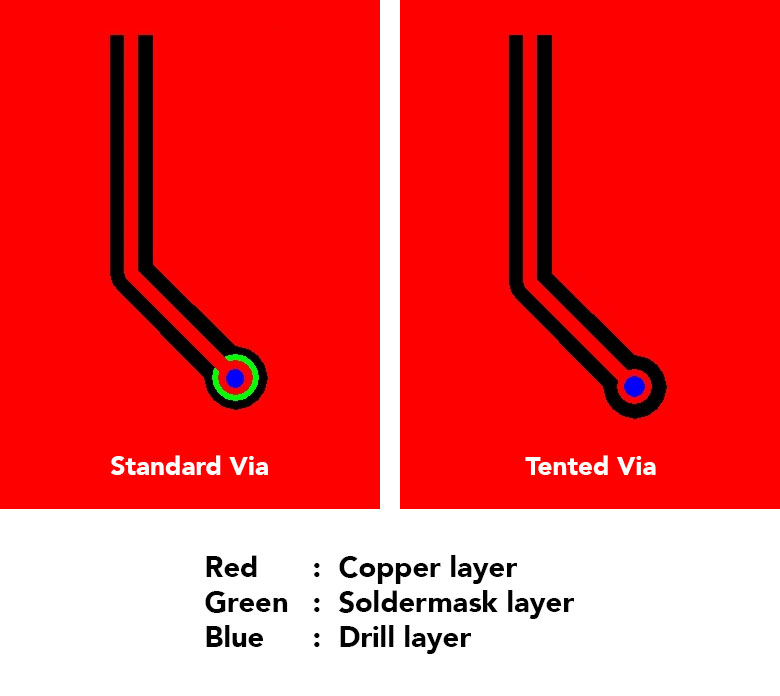
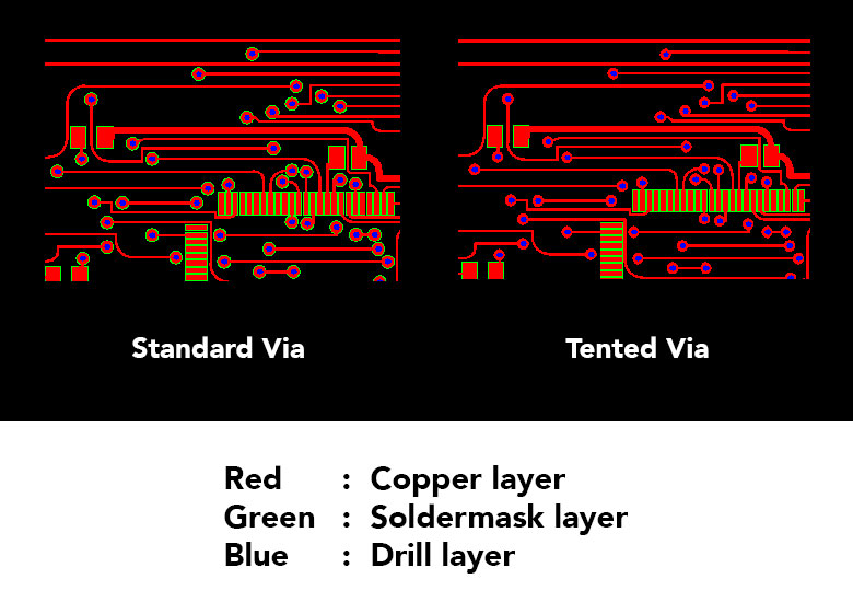
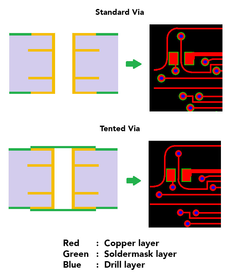
A via tenting is nothing but covering its annular copper ring with solder resist, also known as LPI (Liquid Photo Imageable) ink.
PCB designers need to remove solder mask pad from via location in their design, which comfortably enables QualiEco engineers to provide via tenting. This is why, it is considered as the easiest and absolutely FREE process. In this process, we can only ensure that the annular copper ring is covered with solder resist ink. The surface of the hole may or may not be covered with the solder resist ink.
Pros
No cost involved
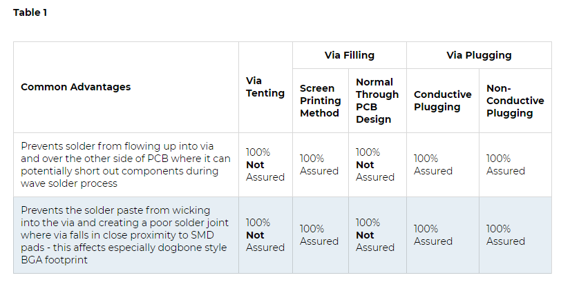
Refer Table 1 for common advantages and its assurance level
Cons
Since via tenting is achieved by just removing solder mask pad from design, applying solder resist ink (LPI) may not cover the surface of the hole completely. If layer of LPI solder mask is broken over via hole, it provides a way for corrosive flux, moisture and other chemicals to enter. These impurities can finally be trapped, which increases the possibility of via failure as the corrosion starts eating plated copper inside the barrel.
With the popularity of No-Clean flux in SMT assembly these days, the possibility of contamination has been reduced significantly. However, corrosive Water-Clean flux still prevails in TH assembly and can cause problem. To tackle this issue, it is best to use any surface finish but HASL, which will reduce the risk at a greater extent.
Via Filling (LPI method)
Basics
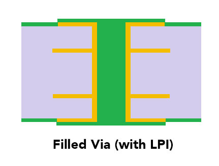
Apart from tenting, via holes are also filled with solder resist ink (LPI) in this process. In the following are the two processes that can achieve this -
Screen Printing Process
In this process, a drilled ALU sheet is used to push standard solder resist ink (LPI) into via holes that need to be filled. The solder mask process is carried out after this screen printing process. 100% guaranteed result is assured in this process.
Pros
Cheaper in cost compared to via plugging (conductive or non-conductive) process
Ideal if the motive is only to fill via with 100% assurance
Refer Table 1 for common advantages and its assurance level
Cons
Not suitable for Via In Pad process (i.e. for active via)
Normal Through PCB design
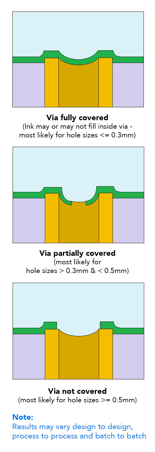
When PCB designers remove solder mask pad from the via location, it is assumed that during the standard solder mask process, solder resist ink (LPI) will flow inside the hole and over the annular ring and eventually fill the via.
It is very important to note that the smaller the via hole size, the better the result will be. Via hole sizes less than 0.3mm have the best chance of getting filled, while between 0.3mm to 0.5mm sizes, filling results may vary depending on the surface tension.
Pros
No cost involved because via filling is achieved through normal PCB design (screen printing process costs extra)
Refer Table 1 for common advantages and its assurance level
Cons
Not suitable if a design demands 100% assured filled via
Not suitable for Via In Pad process (for active via) and therefore not recommended for highly complex designs having a fine pitch BGA.
Via Plugging (Via In Pad – Conductive or Non-Conductive)
Basics
In the race to manufacture products more and more compact and advanced, Electronic engineers are facing a tremendous challenge to design circuit boards that take less space without compromising performance. Therefore, BGA packages with tighter spacing are becoming popular day-by-day.
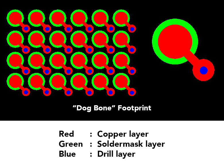
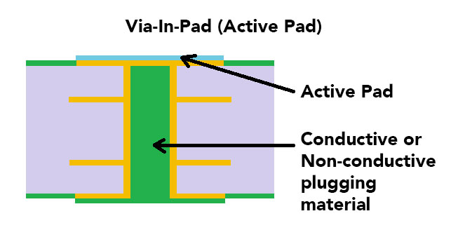
Instead of using the standard “dog bone” footprint, WHERE signals are transferred from the BGA pad to via and then from via to other layers, the via can be drilled directly into the BGA pad. This makes the routing of track work tighter and simpler in designing PCBs as the surface of via itself becomes BGA pad allowing it to be treated as a normal SMD pad for soldering. This process is called “Via In Pad” while the pad is called an "Active Pad".
Types
Broadly, there are two types of via plugging available depending on the material that is used in plugging process (1) Non-conductive via plugging (2) Conductive via plugging. Out of these two, the most common and widely preferable is non-conductive via plugging.
Conductive Via Plugging
For PCB designs that require to transfer high amount of heat or current from one side of the board to another, conductive via plugging is a handy solution. It can also be used to dissipate excessive heat generated underneath some components. The metallic nature of the fill will naturally wick heat away from the chip to the other side of the board in many ways like a radiator.
Pros
Heat sink or transfer where other conventional methods are impractical e.g. underneath the chip component
Increased current carrying capacity due to higher thermal conductivity (between 3.5 to 15 W/mK) of the conductive material
Refer Table 1 for common advantages and its assurance level
Cons
High instability of copper pad and copper plating inside the via hole barrel. This occurs due to the difference in CTE (coefficient of thermal expansion) value of conductive material and laminate surrounding it. When the PCB goes through thermal cycles, metal will heat and expand more rapidly than surrounding laminate, which can cause a fracture between pad and via hole barrel and lead to an open circuit
Thermal conductivity is not too high (compared to electroplated copper that has thermal conductivity of more than 250W/mK) so it is possible to add a few more vias and avoid this process to more reliable non-conductive via plugging
More expensive than non-conductive via plugging
Not in good demand so only few manufacturers can offer
Non-Conductive Via Plugging OR Epoxy Resin Plugging
This is the most common and popular method of via plugging, especially for Via In Pad process. The barrel of via hole is filled with non-conductive material like Peters "PP 2795", San-Ei Kagaku "PHP-900 series" and Taiyo Ink "THP-100 DX1" plugging paste. Selection of the material depends on the CTE value, availability, specific design requirements and type of plugging machine. Thermal conductivity of non-conductive material is normally close to 0.25 W/mK.
A common misconception about non-conductive via plugging is that the via will either not pass any current or only a weak electrical signal, which is absolutely not correct. The via will still be plated as normal before non-conductive material plugged inside via. It means, via will work as normal as in any other standard PCB.
Pros
Prevents solder or any other contaminants from entering into via
Provides strength and structural support to active pads (Via In Pad process)
Offers better stability and reliability of pad and via due to close match of CTE between filling material and surrounded laminate when comparing the same with conductive material
Cheaper than conductive plugging because of its wider usage and popularity
Refer Table 1 for common advantages and its assurance level
Cons
Lower thermal conductivity of filling material makes it unsuitable for certain designs
Manufacturing Steps of Via In Pad Process
Via is drilled (through hole or blind)
Fill via with non-conductive material
Surface of plugged via is plated with copper
Newly plated surface is planarized (i.e. flatten and smoothen) so that it becomes even with surrounding copper surface
Final surface-finish applied i.e. ENIG or ENEPIG or Immersion Silver etc.
Solderable surface mount pad is ready that can also pass signal to inner layers eliminating the need to rout the signal through the via
Capabilities
Payment Methods
Specials Price
Carriers
Support Hobbyist
Certificate
Customer Support
Follow Us
Tel: 1-905-339-2881
Email: [email protected] , [email protected]
Copyright Gold Phoenix PCB Co., Ltd. 2011 - 2023
Tel: 1-905-339-2881 Email: [email protected] , [email protected]
Quality Control System
|
Products/Service
|
Friendly Links
Copyright Gold Phoenix PCB Co., Ltd. 2011 - 2023


