MEMBRANE SWITCH CIRCUIT
A membrane switch is a particular type of custom switch assembly built to either open or close an electrical circuit's conducting path. Each layer in the assembly serves its own unique purpose. Custom features can easily be added with the design considerations. Below are the principles of membrane switch circuit design, and best practices you should follow to guarantee success.
Graphical Overlays
Within the context of a membrane switch, graphic overlays are the outermost layer. Graphical overlays can be made from a wide range of different materials, including polyesters, polycarbonate, and more. Various types of adhesives are also employed to secure the graphical overlays in place. Graphic overlays do not have any live electrical circuits or wires whatsoever. They are exclusively printed artwork using polyester or polycarbonate and adhesives.
Circuit Layers
Commonly, a membrane switch's circuit layer is constructed from polyester (PET). Screen printed silver ink is used as the conductive element on the circuit. Depending on the situation, if a higher reliability solution is desired. FPC circuits use etched copper as the circuit material.
The circuit layer itself can assemble surface-mounted components such as LEDs and/or resistors to function as intended within the membrane switch circuit. This layer is also what makes it possible for any buttons, keys, and other inputs to function appropriately within the laminated layers of the membrane.
ZIF Connectors
A ZIF connector is one option used to electrically connect a membrane switch with its parent PCBA. It is one of the most inexpensive/ most widely used ways to do so. These connectors are constructed using screened ink or etched copper. Those materials are then laminated similarly to the process used for flex circuits. The number of pins on a ZIF connector is directly related to the number of switches required for the operation of the circuit. Each pin is clearly designated on the associated electrical schematic.

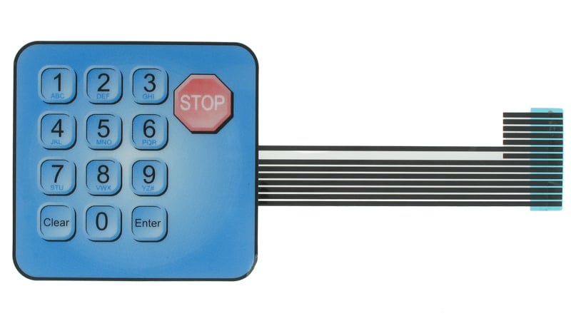
Membrane switch with a graphic overlay and ZIF termination tails
Keep-Out Areas
Keep-out area is an important area on a circuit WHERE there can be absolutely no electrical traces present. Indeed, this is one of the most critical best practices of membrane switch circuit design. No components should be added in these zones at all to guarantee the successful operation of the circuit.
Likewise, LEDs and domes should never be added to areas of the product where there are pre-existing circuit traces or too close to the edge of the membrane switch. There needs to be space to mount the component and properly attach it to the circuit.

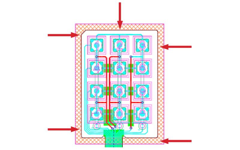
Perimeter keep out zone on a waterproof membrane switch.
Switch Matrix
A switch matrix is a component made up of various circuits, all of which have been arranged in a precise grid of rows and columns. This is done to make it easy to set up connections at any point where circuits interact with one another. This design helps optimize the membrane switch and increases the number of buttons possible with a given pin count. Using a switch matrix can be an effective way to reduce both the overall pin count and the number of channels that are needed for operation. Fewer pins allow you to work with smaller connectors, which can reduce the complexity and the overall cost of the end product.
Waterproofing Membrane Switch
If a membrane switch designed for outdoor use, a waterproof design is usually a requirement. Industry-standard recommends this design should meet IP54 standards, although meeting higher requirements is encouraged.
The circuit of waterproof membrane switch needs a perimeter keep-out zone for sealing purposes. Extra space must be built into the design ranging from between 2mm to 6mm going all the way around the outermost edge of the circuit. This will leave enough room so that a waterproof seal can be added without impacting the circuitry.
Summary
Membrane switch circuits offer the flexibility required for a wide range of different end user applications. The use of a switch matrix circuit layout, paying attention to waterproofing and recognizing keep-out areas are all critically important to make sure that the finished product meets all program objectives.
Capabilities
Payment Methods
Specials Price
Carriers
Support Hobbyist
Certificate
Customer Support
Follow Us
Tel: 1-905-339-2881
Email: [email protected] , [email protected]
Copyright Gold Phoenix PCB Co., Ltd. 2011 - 2023
Tel: 1-905-339-2881 Email: [email protected] , [email protected]
Quality Control System
|
Products/Service
|
Friendly Links
Copyright Gold Phoenix PCB Co., Ltd. 2011 - 2023


